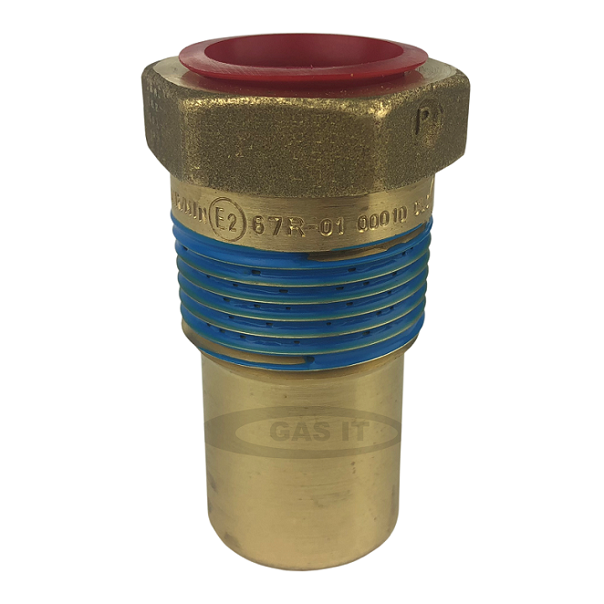
Pressure Relief Valve ( Valve Fitment 2 )

This is the 2nd valve to be fitted in this order.
When fitting the pressure relief valve into the tank you need to make sure the thread in the tank is clean.
On the brass tanks valves with a thread there is normally a blue sealant paste which has been applied at the factory. We still recommend you use a liquid PTFE paste as an extra part when fitting the valve ( Added to the blue on the valve ) as this will add sealing the valve in the tank plus it also acts a lubricant to help install it.
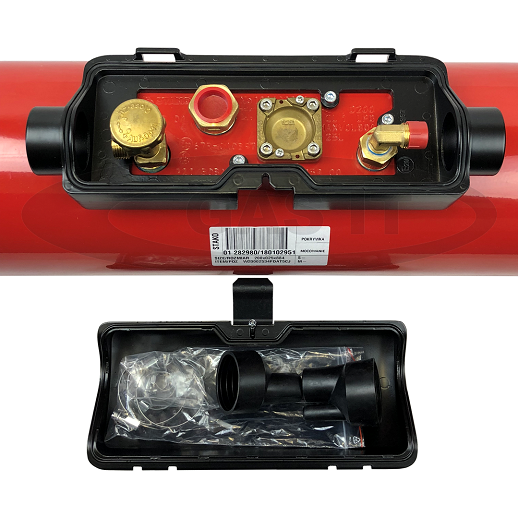
This valve must be fitted when you have the valve plate facing upwards ( at 12 o clock ) and it must be horizontal so all the valves drop down inside.
Make sure you install it to the correct manufactures torque setting.
Please read and follow the attached manufactures instructions for the required torque setting and for correct fitment of the valve - See attached document.
We find that for the installation of the 3 valves ( 1, 2 & 3 ) into the tank its self we do 5 complete turns and then the extra turn that might be needed to point the valve in the right direction as per the picture above
If you are unsure please contact GAS IT technical support before proceeding further as we can not be held responsible for any damage or incorrect functionality of the valves when you have fitted them in the tank.
Once all valves are fitted, please carry out a leak check using air, then drain the air and then carry out a further leak check with LPG vapour - using certified Leak detection spray on all the joints you have assembled. Do not fill with liquid LPG until you are satisfied the tank is LPG vapour tight first and then only fill using no more than 2 ltrs of Liquid LPG to allow further leak checking. Then continue to follow the install set up instructions here on the on the GAS IT knowledgebase here