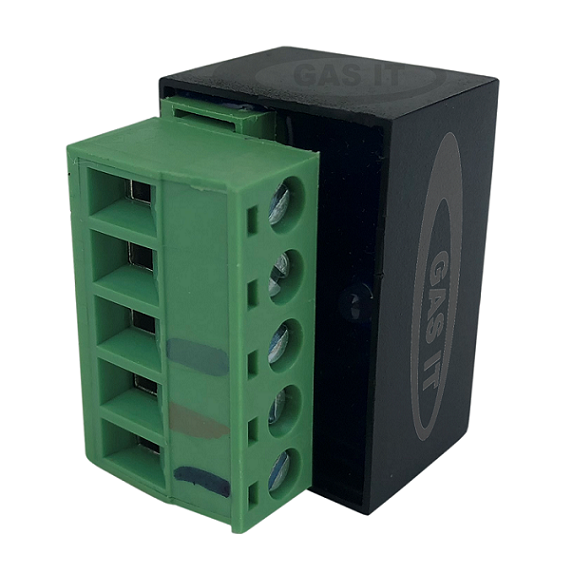
ULCD 2.0 ( GI-ELE-063 ) Wiring (Version 2)

Find attached the wiring instructions for the GAS IT ULCD 2.0 unit when using a simple rocker type switch ( GAS IT part number GI-ELE-013.). The attached wiring diagram must NOT be used when a GAS IT 4 wire LED display is used ( If you are using a 4 wire LEd with a yellow wire then the yellow wire goes to pin 3 only and not the tank solonoid - please see pin numbering below )
This GAS IT ECU ( Ultra Low Current Device 2.0 ) is designed to control the GAS IT Underslung LPG gas tanks fitted with the GAS IT electronic outlet device to turn the gas on and off remotely. ( GAS IT part Number GI-ELE-063) in a controlled manor. This is not to be confused with our previous version of ULCD, PT number GI-ELE-008, which required a negative trigger on pin 3 ( this new 2.0 version requires a 12v positive + trigger on Pin 3 now to activate it )
This is not just a relay.
It is a fully designed ECU that will operate the GAS IT tanks electronically outlet solenoid in the most efficient manor to allow the vehicles battery to last significantly longer than if the solenoid was just opened using a 12 volt switch or relay.
Here's what it does : As the solenoid in our GAS IT tanks is opening and closing at full Gas tank pressure we need to fire the open operation of the gas tanks solenoid with full battery voltage and full opening current ( approx 1.2 amp ) to lift against the tanks gas pressure, but the ULCD is then designed to automatically lower the holding current of the solenoid in a controlled manor to approximately 0.07 of a amp there after. This is important on a vehicle that is used for wild camping or off electric for any length of time for example ( to charge the battery ) as the ULCD's lower holding current means the vehicles battery ( a 110 amp leisure battery for example ) will last for approximately 33 days with the gas on full time before even half of the battery power ( amps ) are used.
This wiring diagram attached is for use with a 12 volt simple rocker switch as this links pin 3 & 5 together so the rocker switch carries the main supply current / load but if you are using this ULCD 2.0 with a 4 wire GAS IT LED display ( which comes with a switched yellow low current output wire ) then please do not follow the wiring diagram as connecting pin 3 & 5 together will blow the 4 wire LED switch unit as the small think yellow wires and ECU inside is not designed to carry the high currents the tank solenoid requires.
Here is the correct pin wiring for the ULCD when using the 4 wire LED display with switched output :-
1) Tank Solenoid Negative
2) Tank Solenoid Positive
3) Yellow Wire from LED switch ( if using a 4 wire LED output )
4) Vehicle Earth
5) Direct to 12 Volt fused Battery Supply.
PIN 3 & 5 ARE NOT CONNECT TOGETHER WHEN USING THE 4 WIRE GAS IT LED SWITCHED YELLOW WIRE OUTPUT DISPLAY UNIT.
Please note whilst the ULCD is a waterproof unit, we highly recommend placing the ULCD unit in a dry location which can be either near or away from the tank. Also to aid wiring the green plug (with screw terminals ) can be removed and disconnected from the black electronic unit itself.